


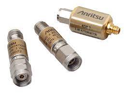
Attenuator classification
There are two types of attenuators: passive attenuators and active attenuators. The active attenuator cooperates with other thermal components to form a variable attenuator, which is used in the automatic gain or slope control circuit in the amplifier. Passive attenuators include fixed attenuators and adjustable attenuators. Fixed attenuators are composed of resistors and do not affect frequency characteristics. They are usually composed of T-type or π-type networks. With the development of modern electronic technology, fast adjusting attenuators are needed in many occasions.
Basic uses of attenuator
1) Control the power level: Control the output power of the local oscillator in the microwave superheterodyne receiver to obtain the best noise figure and conversion loss to achieve the best reception effect.
2) Decoupling component: as a decoupling component between the oscillator and the load.
3) Relative standard: As a relative standard for comparing power levels.
4) Jumping attenuator used in radar anti-jamming: It is a variable attenuator whose attenuation can be changed suddenly. It usually does not introduce attenuation, but suddenly increases attenuation when encountering external interference.
Attenuator related parameters
1) Attenuation: It is used to describe the amount of signal reduction from one end to the other during transmission. It can be expressed in multiples or decibels.
2) VSWR: Equal to the ratio of the characteristic impedance to the impedance of the load connected to the output end of the transmission line.
3) Maximum average power: When the attenuator output terminal is connected to the characteristic impedance, the maximum power that can be added to the attenuator input terminal for a long time at the specified maximum operating temperature. When the operating temperature drops to 20ºC and the input power drops to 10mW, other indicators of the attenuator should not change.
4) Power coefficient of insertion loss: When the input power is from 10mW to the rated power, the change in insertion loss (dB).
5) Maximum peak power: When the attenuator output terminal is connected to the characteristic impedance, the maximum peak power of 5ms pulse width applied to the input terminal of the attenuator at the specified maximum operating temperature within the specified time. When the operating temperature drops to 20ºC and the input power drops to 10mW, other indicators of the attenuator should not change.
6) Temperature coefficient: The maximum change in insertion loss within the maximum operating temperature range, expressed in dB/ºC.
7) Shock and vibration: The attenuator must withstand shock and vibration tests in three directions.
8) Frequency response of insertion loss: At 20ºC, the change in loss value (dB) in the entire frequency range.
9) Upper limit of operating temperature: The highest temperature (ºC) at which the attenuator works at the maximum input power.
10) The deviation of the nominal insertion loss: the deviation between the measured insertion loss and the nominal value when the input power is 10mW at 20ºC.
11) Connector life: The number of normal connections/disconnections; all electrical and mechanical indicators should meet the indicator requirements within the specified life.
12) Intermodulation distortion: Intermodulation distortion is composed of spurious signals, which are caused by non-linear factors in the device. Especially need to pay attention to is the third-order intermodulation distortion, because the third-order intermodulation product is the largest and cannot be filtered out. The third-order intermodulation level test method is to inject two equal amplitude pure signals (f1 and f2) into the device under test, and the third-order intermodulation will appear at 2f1-f2 and 2f2-f1 of the output spectrum. The third-order intermodulation product is defined by the relative size of f1 or f2, which is represented by -dBc.
Summarized by Easybom.
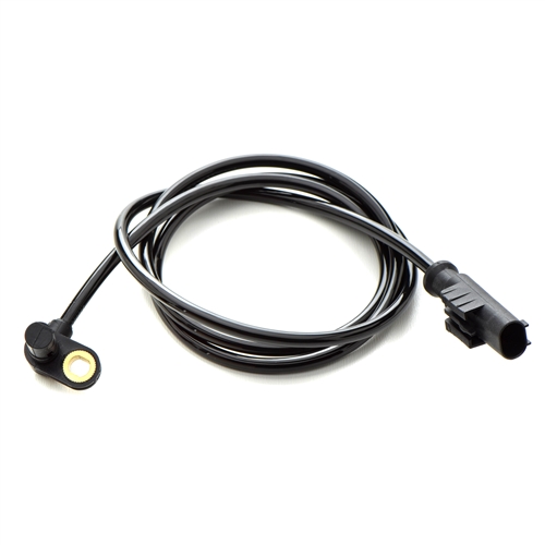


The study titled, “Global Attenuator Cables Market” provides an extraordinary analysis for evaluating the industry, highlighting opportunities and supporting strategic & skillful decision-making.The report ‘Global Attenuator Cables Market’ provides deep insights for ‘Attenuator Cables Market’ market based on decisive aspects of a market study.
Location analytics of the ‘Attenuator Cables Market’ in report majorly highlighted are Asia-Pacific, North America, Europe, South America and Middle East & Africa for reviewing and studying markets periodically.
Moreover, report precisely covers different market segments like definition, type & application.Request sample Pages @ http://www.orbisresearch.com/contacts/request-sample/2328660 Attenuator Cables Market guided by following key players:3MMeca ElectronicsHeliaxAtlan TecRFFibertronicsFairview Microwave Inc.Shilpi Cable Technologies LimitedSmiths GroupHasco, Inc.Circuit Foundry LLP (Attenuator Manufacturer)Koma ElectronikStromKultThe report on ‘Attenuator Cables Market’ also offers detailed study for the key players or vendors dwelling in the market.
It reveals the company information, business overview, sales data and product specifications about manufacturers that can help make business predictions.Attenuator Cables Market Types:Fiber Optic CableCoaxial CableOthersMarket research report on ‘Attenuator Cables Market’ is inclusive of all the important aspect of the market study performed through SWOT and Porter's Five Forces methodology.
Every single market has got a set of manufacturers, vendors and consumers defining a particular market along with their each and every move.
When reports are product based, they also include information on sales channel, distributors, traders and dealers.