


Introduction: 3D Spatial Data as the Engine of Industrial Facility Intelligence
Industrial and manufacturing facilities rank among the most geometrically demanding environments in the built world. Dense pipe racks, pressurized vessels, multilevel conveyor systems and interconnected MEP networks accumulate. Over decades of modifications each layer adds complexity that legacy drawings fail to capture. Field modifications, equipment replacements, and undocumented changes create deviations that impact project execution at every stage.
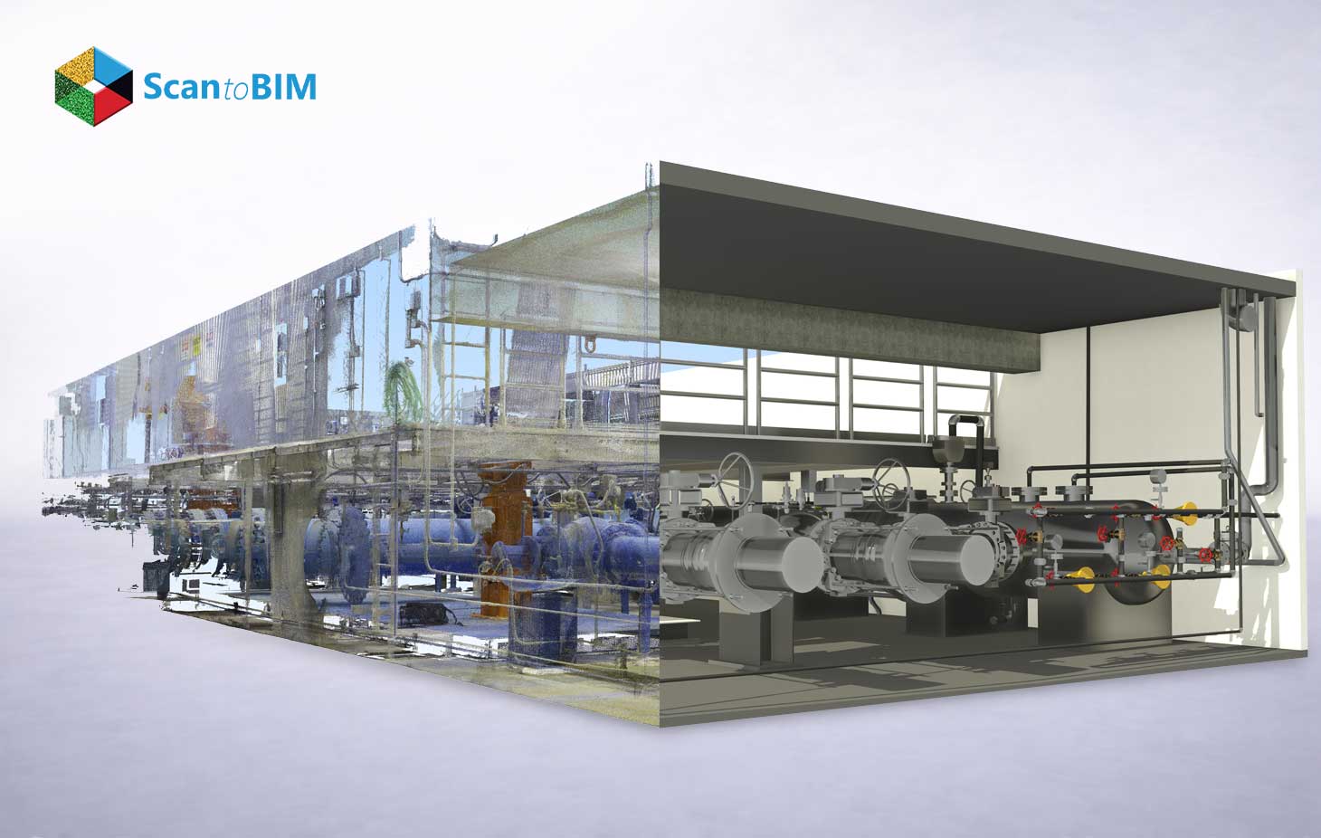
Digital construction technology has repositioned how engineering teams approach these challenges. Rather than working from floor plans that predate several rounds of retrofits, project teams now capture the physical reality of a plant using LiDAR and transform that raw data into intelligent parametric models. Point cloud datasets contain millions of XYZ coordinates and reflectivity intensity values captured through LiDAR and photogrammetry technologies representing physical assets such as steel structures, process piping, conveyor systems, and heavy machinery at millimeter-level fidelity.
The demand for point cloud to bim services continues to accelerate as asset owners recognize that inaccurate facility documentation produces costly field clashes, delayed commissioning, and failed equipment installations. Industrial BIM modeling starts with captured scan data and ends with a fully coordinated, data-rich digital asset ready for design, construction, and operations, one that replaces fragmented documentation with a unified digital representation of actual site conditions.
Why Industrial and Manufacturing Facilities Require Accurate BIM Models
Manufacturing plants depend on tightly interlocked systems such as process lines, bulk material handling, utilities, structure, and building services occupy shared space with strict clearances. These facilities experience continuous modification, new equipment arrives, piping reroutes, electrical panels shift, and structural supports get added across production cycles, all without systematic drawing updates. This creates a dangerous gap between what documentation records and what the facility physically contains.
When engineering teams plan a new equipment installation using drawings that predate several rounds of plant upgrades, the outcome is predictable: interference conflicts emerge on-site, production shuts down for unplanned field modifications, and rework costs reach into the millions. As-Built BIM modeling closes this gap by capturing the actual physical state of the plant at a precise moment in time, producing a model geometry that reflects reality down to the pipe support bracket and nozzle orientation.
The parametric models produced through As-Built BIM modeling carry geometry, elevation data, spatial relationships, and object properties that match the true physical plant from structural steel framing elevations to the exact centerline coordinates of every process pipe. An As-Built model records exact centerlines, connection points, and envelope volumes for equipment and MEP systems. So new skids, pipe runs, or cable routes connect in the correct positions on the first attempt. Equipment installation clashes surface at the design review stage, long before crews mobilize on-site supporting fire safety, escape routes, and hazardous area zoning documentation simultaneously.
How Point Cloud to BIM Works for Industrial Facilities
The conversion of raw scan data into a coordinated BIM model follows a defined technical sequence. Each phase builds on the previous and quality verification runs throughout the entire pipeline.
Phase 1: Site Scanning Laser scanners capture spatial data across the full extent of the facility, covering process areas, elevated platforms, confined equipment rooms, and outdoor tank farms. Technicians position scanners strategically to achieve overlapping coverage across equipment clusters, pipe racks and structural frames. The scanner records XYZ coordinates and reflectivity intensity values for every surface in its field of view, producing point clouds with densities reaching several billion points per project.
Phase 2: Registration and Coordinate Unification Individual scan files merge into a single unified point cloud. Registration software such as Leica Cyclone, FARO SCENE, and Autodesk ReCap align each scan into a unified global coordinate system. This is achieved using control target networks and point cloud matching algorithms to make sure of accurate positioning. Survey control networks align plant coordinate systems, grids, and global references, so models integrate civil, building, and process scopes without later reprojection.
Phase 3: Parametric BIM modeling involves referencing the registered point cloud in Autodesk Revit to create parametric families for facility elements. These include structural steel, pressure vessel skirts, instrument stands, cable trays, pipe rack columns, ducts, and electrical panels with accurate geometry, elevation, and dimensions. Parametric families carry attributes such as sizes, connection standards, material codes, and ID tags, so downstream users filter, schedule, and quantify plant assets directly from the model. The point cloud to bim workflow at the parametric modeling stage demands specialists who understand both industrial process systems and BIM authoring tools at an expert level.
Phase 4: Deviation Analysis and QA The completed model undergoes overlay comparison against the source point cloud. Deviation reports flag any geometry outside the project's tolerance threshold. Commonly ±6 mm for process piping and ±3 mm for fabrication-level structural members. Many industrial projects adopt sub-centimeter tolerances for critical interfaces such as nozzles, tie ins, and equipment seats. So installation crews align prefabricated components quickly on-site.
Phase 5: Deliverable packaging provides project teams with Revit models, IFC exports, Navisworks coordination files, and 2D drawings derived from 3D geometry. It also includes equipment datasheets linked to BIM objects, discipline models, and open formats compatible with tools like AutoCAD Plant 3D and PDMS/E3D.
Role of 3D Laser Scanning in Industrial Plants
The accuracy of any BIM model depends entirely on the quality of its source point cloud. Industrial environments require scanners that can capture complex, occluded geometry over long ranges with sub-millimeter angular resolution. They must operate effectively in challenging conditions such as dust, reflective steel, high-contrast lighting and hazardous areas.
Understanding the specific laser scanners used for industrial projects allows project teams to select hardware matched to each facility's geometry, size, and safety classification.
- Range accuracy: ±1–3 mm at distances up to 80 m
- Scan speed: Up to 2 million points per second on premium terrestrial units
- Angular resolution: Configurable down to 0.009° for dense pipe capture
- Environmental rating: IP54 minimum for dust and moisture exposed plant environments
- ATEX compliance: Intrinsically safe variants for Zone 1 and Zone 2 classified areas
- Operating temperature tolerance: Rated for extreme thermal environments in process plants
TLS units including the Leica RTC360, FARO Focus Premium and Trimble X7 deliver the point density that industrial pipe modeling requires. Mobile mapping systems such as the Leica BLK2GO and GeoSLAM ZEB Horizon extend coverage into narrow pipe corridors and underground utility tunnels. Where tripod scanners cannot physically operate. Drone LiDAR captures elevated structures, rooftop HVAC arrays, and cooling towers through safe remote operation during live plant conditions.
For pipe racks, laser scanning industrial plants scan positions every 8–12 meters along the rack's length to capture full circumferential geometry across all pipe diameters. Pressure vessels demand wrap-around scanning to document nozzle orientations and platform attachment locations. Conveyor systems require both plan and cross-section coverage to document head and tail pulley positions, support structure geometry, and belt transfer points. Scanning teams schedule captures during steady-state operating conditions and planned maintenance shutdowns to maximize data quality across vibration-sensitive areas.
Key Benefits of Point Cloud to BIM for Manufacturing Facilities
Point cloud to bim for industrial facilities delivers measurable operational and financial value across the full project lifecycle from initial design through long-term asset management. Manufacturing facilities handle high-throughput flows of materials and products. So spatial optimization transforms their profitability and resilience.
Facility planners use models to analyze available floor space, optimize aisle widths for material handling equipment, and identify dead zones suitable for vertical equipment expansion. Maintenance teams access asset data through model linked databases, transforming BIM from a design tool into a live operational facility management platform. Every expansion, retrofit, or technology upgrade draws from a single consistent source one coordinated digital twin that supports simulations, energy analysis, and fire safety documentation.
Applications in Industrial and Manufacturing Projects
Industrial scan to bim services address project types that span the full facility capital investment cycle, from greenfield adjunct buildings to brownfield modernization and live operational support.
Brownfield expansion projects engineering teams connect new process modules, pipe bridges, transfer towers, and new buildings to existing pipe racks, structural frames, and electrical distribution systems. The BIM model of the existing plant serves as the coordination baseline for all new design work enabling consistent planning and integration. Automated clash detection identifies spatial conflicts early, producing a fabrication ready design package before site mobilization and crane positioning.
Seismic retrofitting projects use BIM models to analyze existing structural systems and design reinforcement schemes that thread between active process equipment. The model quantifies exact steel tonnage, bolt connection details, weld configurations at each intervention point, and the construction sequence. That maintains production continuity throughout the retrofit campaign, supporting structural analysis models with updated layouts and connection configurations.
MEP coordination in manufacturing plants routes new HVAC duct runs, process piping headers, compressed air distribution, chilled water lines, and cable tray networks through congested ceiling and wall spaces. Additional recurring applications include line relocations in automotive and FMCG plants, high-purity process upgrades in pharmaceutical and food facilities, energy efficiency retrofits for boilers and waste heat recovery systems, and digital twin development with linked sensor and IoT control system data.
Challenges in Industrial Point Cloud to BIM Projects
Scan to bim challenges in industrial environments differ in scale and technical complexity from commercial building projects. Teams that understand these obstacles in advance build mitigation strategies directly into project plans.
High-vibration environments: Operating compressors, rotating machinery, and conveyor drives generate scan noise that appears as point cloud artifacts. Scheduling scans during planned maintenance shutdowns and applying registration stabilization techniques across setups eliminates this source of data degradation.
Dense piping occlusion: Process pipe racks with 40–60 lines per bay create occlusion shadows behind pipe clusters. Supplementary scan positions, elevated setups, and mobile scanning achieve full surface coverage across congested rack bays.
File size management: Industrial point clouds for a 50,000 m² facility exceed 500 GB and reach terabyte scale for large campuses. Point cloud decimation and tiling strategies manage file sizes within Revit's processing capacity. While multi-user workstation configurations handle large dataset workflows.
Reflective surfaces: Polished stainless steel tanks and glass panels generate scan noise from specular reflection. Scan parameter adjustments and post-processing intensity filters isolate clean surface data from reflective interference.
Hazardous zone access: Classified ATEX areas restrict standard scanning equipment and limit occupancy dwell times. Intrinsically safe scanners approved for Zone 1 and Zone 2 environments and remote tripod configurations provide full coverage in these restricted areas.
Multi-system segmentation: Distinguishing structural steel, process steel, and temporary elements in dense clouds and segmenting overlapping pipes, trays, and cables demands trained specialists. Who interpret point density and intensity variations across complex industrial geometry.
Accuracy and LOD Requirements for Industrial BIM Models
Industrial projects demand higher modeling fidelity than standard architectural projects. The LOD framework defines the geometric and informational content of every BIM element, and industrial specifications push requirements toward the upper end of the scale defined explicitly in every project's BIM Execution Plan.
LOD 350 Coordination-Ready Geometry: At LOD 350, every pipe, duct, conduit, and structural member carries accurate physical area data. Connection interfaces between systems appear in the model, enabling full mechanical and electrical clash detection with sub-centimeter positional accuracy. This LOD serves MEP coordination workflows, plant layout approval submissions, lifting studies, and construction package preparation.
LOD 400 Fabrication-Level Detail: LOD 400 models contain complete fabrication geometry. Pipe isometrics with spool designations extract directly from the model. Structural steel connection details include bolt patterns, weld symbols, and connection plate geometry with shop drawing accuracy. Equipment models include nozzle schedules, orientation data, and dimensional reference datasets that procurement teams use directly for vendor coordination and material delivery planning.
AI in BIM modeling accelerates LOD 400 delivery through automated pipe centerline extraction and intelligent object recognition from point cloud density patterns. It also uses cylinder and plane detection algorithms along with parametric family placement for standard industrial components. AI-driven pipe routing tools reduce manual modeling time for repetitive pipe rack geometry by 40–60%, with statistical fitting methods refining element locations against point clusters so final coordinates remain consistent with scan data. Skilled modeling hours focus on complex, non-standard equipment geometries where engineering judgment drives accuracy.
Best Practices for Industrial Scan to BIM Workflows
A disciplined scan to bim workflow separates projects that deliver on schedule from those that accumulate scope and accuracy problems through the delivery cycle.
The following practices define execution standards for industrial projects at scale:
- Unify the coordinate system before scanning begins. All scan positions, control targets, and BIM origin points share one coordinate reference frame from day one of the campaign aligned with plant grids, global survey references, and civil scopes.
- Achieve 30% overlap between adjacent scan positions. Overlap coverage improves registration accuracy and eliminates occlusion gaps in congested pipe areas and behind large equipment.
- Apply point cloud decimation after registration. Reduce point density to 5–10 mm spacing for modeling use, retain full-density coverage at valve clusters and structural connections, and archive the master full-density dataset as the project reference.
- Assign LOD targets per system before modeling begins. Structural systems, process piping, HVAC, and electrical systems receive explicit LOD assignments documented in the BEP preventing scope creep and deliverable ambiguity.
- Run deviation checks at 25%, 50%, and 100% model completion. Three-stage deviation analysis catches geometric drift early and prevents cumulative error from propagating across large, multi-system models. Cloud to model overlay heatmaps visualize out-of-tolerance zones immediately.
- Maintain structured worksharing and model splitting. Large industrial plants require workset discipline, linked file management, and consistent naming conventions so multi-discipline teams collaborate without coordination conflicts.
- Deploy pipe routing AI plugins for standard schedule runs. Autodesk add-ins and dedicated Scan2BIM applications automate fitting insertion and centerline alignment for straight pipe runs in repetitive rack bays, supporting point cloud to BIM automation across repetitive industrial geometry.
Cost Considerations for Industrial Point Cloud to BIM Projects
Point cloud to bim industrial projects require upfront investment in scanning hardware, software licensing and specialized labor. A full facility scan and BIM model for a 30,000 m² chemical processing plant ranges from $80,000 to $250,000 depending on system complexity, LOD requirements, and hazardous area access constraints. High hazard zones, offshore modules, and very tall process units introduce additional ATEX-rated equipment costs and safety compliance overhead.
The financial justification rests entirely on rework cost avoidance. A single field interference discovered during equipment installation requiring pipe rerouting, additional structural support fabrication, and schedule extension costs $15,000 to $100,000 in direct remediation costs, in addition to production downtime exposure. Projects that proceed without scan documentation experience average rework rates of 8–12% of total construction value, consuming substantial contingency budgets when crews discover conflicts after mobilization.
"First-Time-Right" design, powered by accurate BIM models, targets a rework rate below 1%. The difference between 10% rework and 1% rework on a $5 million installation project represents $450,000 in avoided direct costs, a return that exceeds the entire scan to BIM investment on the majority of industrial projects. Accurate prefabrication driven by LOD 400 models further reduces material waste and RFI volumes, compressing procurement and approval cycles. The math is direct: the scan pays for itself within the first avoided rework event, and the model delivers ongoing value across every subsequent capital project that references it.
Choosing the Right Point Cloud to BIM Service Provider
Selecting a laser scan to bim services provider for industrial work requires evaluation across technical capability, industry experience, and operational compliance dimensions. A capable provider combines strong process knowledge with technical excellence in point cloud management and BIM platform proficiency.
The following criteria define a capable industrial-grade provider:
ISO 19650 alignment: BIM data management practices aligned with international information management standards, secure data handling protocols and client BEP requirements communicated transparently from project outset.
Industrial project portfolio: Verified completed projects span refining, chemical processing, food and beverage, pharmaceutical, automotive, and heavy manufacturing sectors. They demonstrate familiarity with hazardous area classifications and operational constraints.
LOD delivery verification: Demonstrated ability to produce LOD 350 and LOD 400 models with client-facing deviation analysis reports and milestone QA/QC documentation.
Point cloud processing infrastructure: Capacity to process 500+ GB to terabyte scale point cloud datasets across multi site industrial campuses with high performance compute resources.
Multidisciplinary delivery team: Process engineers, structural detailers, and BIM coordinators operating under one delivery framework supporting smoother interaction with multi discipline owner and EPC teams.
Safety and access compliance: Operational experience within ATEX zones, permit to work systems, confined space entry protocols, and process safety management frameworks.
Software stack proficiency: Confirmed expertise in Revit, Navisworks, AutoCAD Plant 3D, PDMS/E3D, Leica Cyclone, FARO SCENE and Autodesk ReCap across large multi discipline scopes.
Conclusion: AI-Powered Scan to BIM and the Future of Manufacturing Infrastructure
The manufacturing industry stands at a defining moment in facility documentation and design capability. AI powered scan to bim technology transforms raw point clouds into coordinated, highly detailed BIM models with a speed and accuracy that manual workflows cannot approach detecting building elements so modelers focus on validation, configuration, and engineering-grade decisions rather than repetitive tracing.
Automated object recognition extracts pipe centerlines, identifies structural steel profiles, classifies equipment geometry directly from point cloud density patterns, and propagates pattern driven design changes consistently across repetitive modules such as pipe racks, supports, and equipment skids. Machine learning models trained on industrial component libraries insert parametric families with dimensional accuracy, compressing project delivery timelines from months to weeks. As AI toolsets mature, industrial BIM teams deliver more complex facility models at higher LOD levels with smaller, more specialized workforces.
Manufacturing facility owners who invest in Scan to BIM services today build a digital foundation that supports every future capital project, maintenance program, and operational upgrade decision. The accuracy, coordination intelligence, and lifecycle value embedded in a well-executed BIM model transforms a facility from a static physical asset into a dynamic, data driven operational platform. One that guides every retrofit, expansion, and operational improvement across the manufacturing lifecycle. That transformation starts with a single scan campaign, and it delivers measurable dividends at every stage of the plant's operational life.


