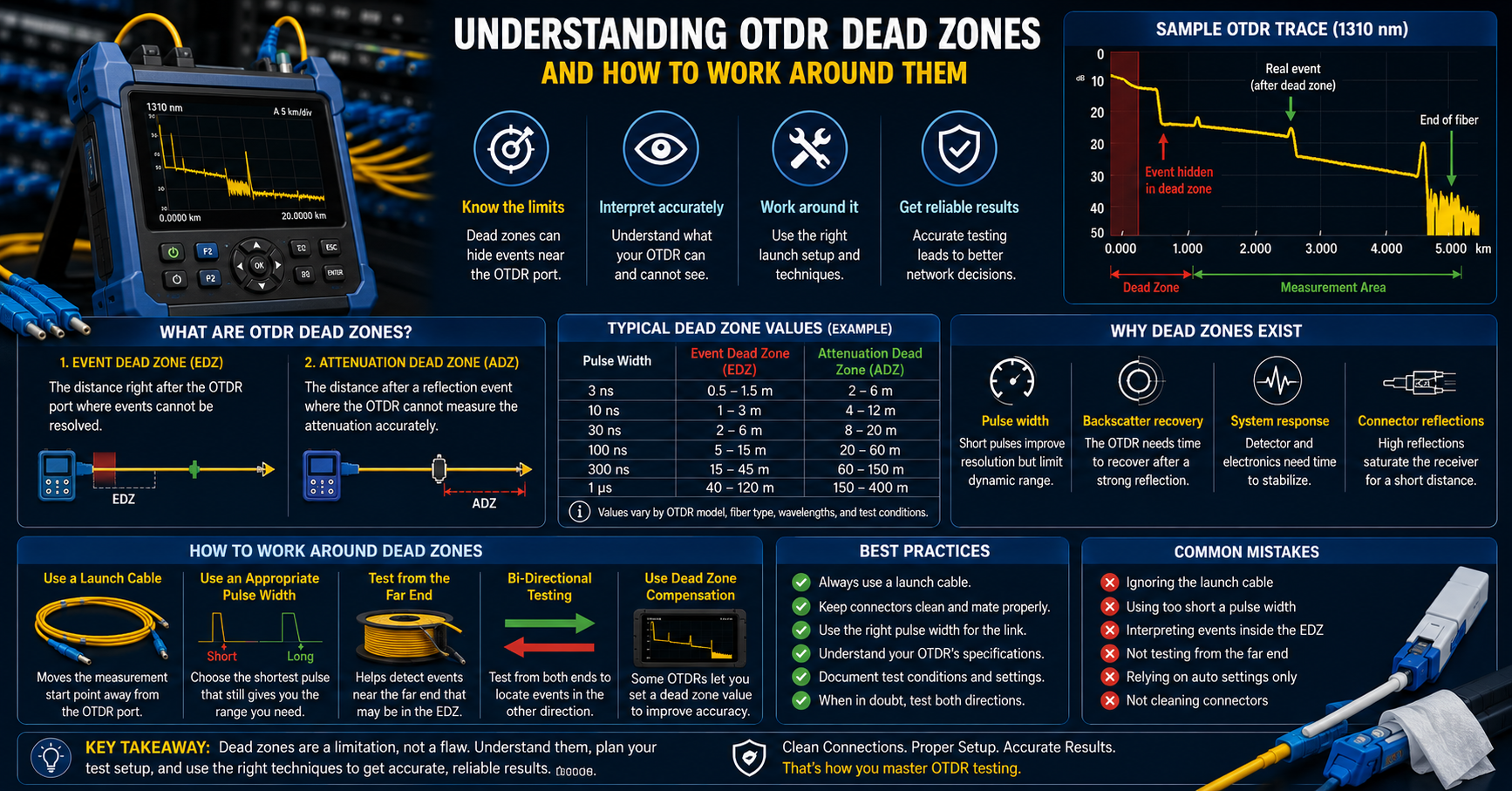
An OTDR dead zone is a section of fiber after an event where the instrument cannot reliably resolve or measure a subsequent event. Strong reflections are the major cause, because a returning Fresnel reflection saturates the photodetector and the receiver then needs time to recover. During that recovery the trace shows a distorted region instead of a usable backscatter.
Dead zones are not a fault in the instrument, and no design removes them completely. They are a physical consequence of firing a pulse of finite duration into glass. Understanding OTDR dead zone behaviour is what separates a fiber with no faults from a fiber whose faults are simply hidden.
What Is an OTDR Dead Zone?
A dead zone starts wherever a large amount of light is reflected straight back toward the instrument, usually a connector, a mechanical splice, or the far end. Rayleigh backscatter from the glass is faint, roughly 40 to 50 dB below the launched pulse. A Fresnel reflection at a glass to air interface is orders of magnitude stronger.
The receiver is tuned to read the faint signal, so the strong one overwhelms it and takes time to settle. That recovery time becomes distance on the trace, because the instrument converts elapsed time into position. Understanding OTDR dead zone limits is therefore a question of geometry, and IEC 61746 governs how these figures are calibrated.
OTDR Event Dead Zone vs OTDR Attenuation Dead Zone
The OTDR event dead zone is the shortest distance after a reflective event at which a second reflective event still registers as separate. For a reflective event, it is measured between the points 1.5 dB below the unsaturated reflection peak. Manufacturers publish it alongside the attenuation figure, and the two answer different questions.
The OTDR attenuation dead zone is the shortest distance at which the trace has settled close enough to normal backscatter for a loss reading to be trusted, conventionally within 0.5 dB. It is normally longer, because the trace needs additional recovery before a loss measurement becomes reliable. Confusing the two is a common field error, because a connector can be visible and still be impossible to characterise.
- Event dead zone answers one question: can two events be seen as separate?
- Attenuation dead zone answers another: can the loss of the second event be trusted?
- Front end dead zone is measured from the instrument port, before any fiber under test.
What Determines OTDR Dead Zone Length
Pulse width is the dominant factor, and the relationship is close to linear. Light moves through single mode fiber at roughly two thirds of its vacuum speed, and the measurement is a round trip, so every 10 nanoseconds of pulse duration works out to about one metre of fiber. That is why the pulse width table on an OTDR tester deserves as much attention as the headline dynamic range.
Reflectance is the second factor, and published dead zone figures are conditional on it. Lower reflectance events generally produce shorter dead zones under otherwise comparable test conditions, so a clean end face tends to give a better result than a contaminated one. APC connectors typically produce lower back reflection than UPC interfaces, which is why polish type affects measured OTDR dead zone length.
Shorter pulse width: Tighter dead zone, but less dynamic range and shorter reach.
- Longer pulse width: More reach on long spans, but a longer blind region after every event.
- Higher reflectance: Slower detector recovery and a longer dead zone.
- Clean end faces and APC polish: Generally lower reflectance and better event resolution.
How to Work Around OTDR Dead Zones
Fit a Launch Cable or OTDR Dead Zone Eliminator
A launch cable, sold in some catalogues as an OTDR dead zone eliminator or pulse suppressor, is a spool of known fiber placed between the instrument port and the link under test. Its job is to push the first connector of the real link past the front end dead zone. Without one, that connector is unmeasurable, and it is where installation faults concentrate.
Launch and receive cable lengths vary with fiber length, pulse width, instrument requirements, and the applicable test procedure. A receive cable allows the far end connector to be characterized rather than lost in the end of fiber reflection. Some standards, owners, and acceptance specifications also require bidirectional OTDR testing and averaging.
Clean, Inspect, Then Test
Contamination is the cheapest and most common cause of an unnecessarily long dead zone. A few microns of dust can increase reflectance and worsen receiver recovery, which may push a nearby splice out of measurable range. Understanding OTDR dead zone behaviour at the connector often fixes a trace without changing a single setting, which is why fiber cleaning tools belong in the same case as the test set.
The habit is a loop, not a single step: inspect the end face, clean it if it fails, inspect again before mating. Purpose built cleaners matter because a generic cloth sheds lint and alcohol left to air dry leaves streaks, and both reflect light. Applying the applicable IEC 61300-3-35 inspection criteria gives the crew a consistent basis for evaluating end-face condition.
Change Settings and Cross-Check
Run multiple acquisitions with pulse widths suited to the link. Short pulses improve near end resolution and help separate dense patch panel events, while longer pulses provide more dynamic range for distant events. Modern instruments often combine several pulse widths into a single analysis.
When an event sits inside the dead zone no matter the configuration, another tool answers faster. A visual fault locator floods the fiber with visible red light and can help identify breaks, severe bends, or other faults over short distances, especially near accessible cable ends. For total loss on a short jumper, a two ended measurement stays the reference method.
What Is the Difference Between OTDR and OLTS?
An OLTS, or optical loss test set, pairs a calibrated light source at one end with a power meter at the other and measures total insertion loss end to end. An OTDR is single-ended and rebuilds a map of events from returning light. Only one of the two is affected by dead zones.
Cabling standards treat them as different tiers rather than rivals. Tier 1 certification uses an OLTS to prove the link meets its loss budget, while Tier 2 adds OTDR characterization to help locate and characterize events along the link. On very short links, OLTS provides the end-to-end loss measurement, while OTDR event characterization can be limited by dead-zone effects.
- OLTS: measures end to end insertion loss without the OTDR dead zone limitation, but gives no event location.
- OTDR: event by event map, single ended, locates faults, bounded by dead zone and dynamic range.
- Short jumpers: certify with an OLTS, trace only with launch and receive cables fitted.
Reading Dead Zone Figures on a Datasheet
Every published dead zone number is conditional, valid only under the conditions printed beside it. Manufacturers commonly specify dead zones at a stated reflectance such as −45 dB or −55 dB, but the test condition varies by instrument and fiber type. An EXFO OTDR dead zone specification, like any other brand’s, has to be read with the pulse width and reflectance conditions attached.
The second caveat is that the pulse width producing the best dead zone also gives the least dynamic range. An instrument advertising a sub-metre event dead zone under its shortest-pulse conditions will not necessarily retain that specification at the longer pulse widths needed for extended-range testing. Understanding OTDR dead zone length as a trade off curve is the honest way to read any datasheet.
Test With the Dead Zone in Mind
Dead zones do not make an OTDR unreliable. They define where its answers are valid. A crew that fits launch and receive cables, inspects before every connection, runs both a short and a long pulse, and reaches for an OLTS on short links will give the crew a more reliable basis for interpreting OTDR traces.
Check the dead zone and pulse width figures on your current test set before the next acceptance job, and confirm your launch fiber is long enough for the pulse widths your team actually uses. If either answer is uncertain, start there.
Frequently Asked Questions
What is an OTDR dead zone?
An OTDR dead zone is the stretch of fiber after a reflective event where the instrument cannot detect or measure a following event. A strong Fresnel reflection saturates the receiver, which then needs time to recover. That recovery appears on the trace as distance, so the blind region is quoted in metres.
What is the difference between an event and an attenuation dead zone?
The event dead zone is the shortest distance at which a second reflective event still appears separate. It is normally longer because loss measurement requires the trace to recover sufficiently from the preceding event. Seeing an event on a trace is no guarantee its loss value is trustworthy.
How long is a typical OTDR dead zone?
Modern instruments can publish event dead zones around a metre or below and attenuation dead zones of a few metres under short pulse, specified reflectance conditions. Those datasheet figures grow quickly as pulse width rises. The only useful answer is the one measured at the settings actually used.
Does an OTDR dead zone eliminator remove dead zones completely?
No, a launch cable relocates them rather than removing them. The blind region still exists, but it now sits inside known launch fiber instead of over the first connector of the link. That is usually enough to make the near end measurable.
How long should a launch cable be?
It has to exceed the attenuation dead zone at the pulse width in use, with margin. Launch cable length depends on the OTDR, pulse width, fiber length, connector type, and applicable test procedure. Choose enough length to move the first connector beyond the relevant dead zone, then follow the instrument manufacturer's and project testing requirements. Fiber type and connector polish must match the link.
Why do APC connectors give shorter dead zones?
APC end faces are polished at an angle, so reflected light is steered into the cladding instead of straight back down the core. APC connectors generally produce lower back reflection than comparable UPC interfaces. That can reduce dead zone effects under otherwise similar conditions.
Can dirty connectors make a dead zone longer?
Yes, and it is a frequent cause of an unexpectedly long blind region. Contamination can increase reflectance and worsen receiver recovery, producing a longer or more distorted dead zone. Inspecting and cleaning before every mate is the cheapest fix available for a poor trace.