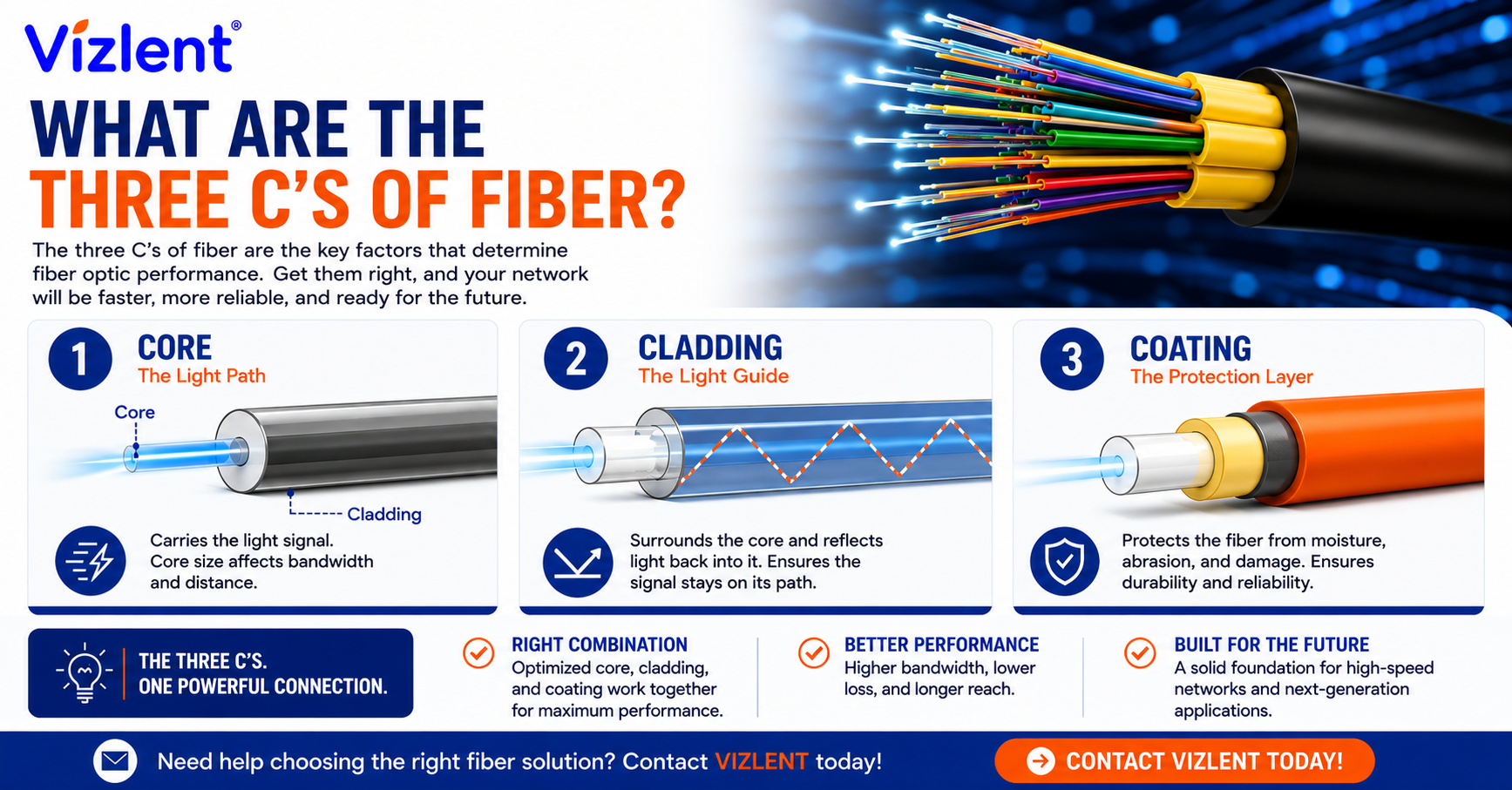
The three C’s of fiber are core, cladding, and coating. The core carries the light, the cladding reflects that light back into the core, and the coating shields the glass from moisture and mechanical damage. Together they form the basic physical structure of an optical fiber, and understanding them is the starting point for everything from connector inspection to splice work.
Throughout this article, fiber refers to optical fiber rather than dietary or textile fiber.
Most people searching this are studying for a cert, prepping for an install, or trying to work out why a brand new patch cord is throwing more loss than expected. All three questions start with the same stack of glass and polymer. So here is the version you get on a job site rather than the one in the textbook.
The 3 C’s of Fiber, Layer by Layer
Picture a pencil. The graphite in the middle is the core, the wood around it is the cladding, and the paint on the outside is the coating. It is a rough analogy, but it gets the geometry across, and geometry is where the rest of the datasheet starts.
Change the core diameter and the fiber’s modal behaviour changes with it. Damage the coating and the glass underneath becomes vulnerable to moisture and surface flaws. These three layers are the physical foundation, though link performance also depends on attenuation, dispersion, connector and splice loss, bend loss, launch conditions, transceiver characteristics, and installation quality.
- Core: roughly 8 to 9 µm for single-mode, 50 µm or 62.5 µm for multimode
- Cladding: 125 µm on standard telecom and datacom fiber, across both fiber types
- Coating: typically a 250 µm acrylate layer applied during manufacturing
Core
The core is the light-guiding center of the fiber, and on single-mode it is astonishingly small. A single-mode core measures about 9 microns across, roughly one tenth the width of a human hair.
That diameter is exactly why contamination causes so much trouble in this trade. A dust particle a few microns wide can sit directly over the core and block part of the light path. Multimode cores run wider at 50 or 62.5 µm, which is one reason multimode tolerates a bit more handling before problems show up.
What goes wrong at the core:
- Dust or lint parked over the light path
- Fingerprint oil smeared across the ferrule during handling
- Pits and chips from mating a dirty connector under spring pressure
Cladding
Cladding is the glass layer bonded around the core, and it carries a slightly lower refractive index than the core does. That index difference produces total internal reflection, the mechanism that keeps light travelling forward down the fiber instead of leaking out the side. No cladding, no waveguide.
At 125 µm, the cladding also sets the mechanical outside diameter of the fiber. Connectors, splice sleeves, and cleavers are built around that number, which is why single-mode and multimode fibers physically fit the same 2.5 mm ferrule. Specialty and non-telecom fibers do use other cladding diameters, but 125 µm covers the vast majority of what gets installed in communications networks.
One point techs sometimes miss: cladding is not empty space in an inspection sense. Debris sitting there can migrate onto the core the moment two ferrules press together. That is why the whole end face gets cleaned, not just the middle.
Coating
The coating is the acrylate polymer layer applied to the fiber during manufacturing, usually while the glass is still being drawn. It protects the surface from moisture, abrasion, and the microscopic flaws that grow into breaks under tension. Strip it off and bare glass becomes remarkably fragile.
It comes off every time a fiber is spliced or terminated, and that bare section is the most vulnerable part of the whole build. Splice protection sleeves and disciplined tray routing exist for exactly that reason. Skip them and the job is running on luck.
The coating itself is usually a dual-layer acrylate:
- Primary coating: soft inner layer that cushions microbending
- Secondary coating: harder outer layer that absorbs handling abuse
A 900 µm tight buffer is a separate thing. It is a protective layer applied over the already-coated fiber for indoor cable and pigtail construction, and it is not one of the three C’s. The full stack reads glass core, glass cladding, primary coating, then buffer or jacket construction, and the exact build varies by fiber design.
Why These Three Layers Matter the Moment You Touch a Connector
All of this turns practical when the second two connectors are mated. A ferrule end face is a cross-section of the three C’s of fiber, polished flat and pressed against an identical face with spring force behind it. Anything sitting between those two faces goes into the loss budget.
Contamination is not a side issue in this industry. It is the dominant one. In a study by NTT Advanced Technology reported by Corning, 98% of installers and 80% of network owners identified fiber connector contamination as the greatest cause of network failure. That is why serious install specs call for cleaning before mating, rather than a shop rag and optimism.
What contamination actually costs:
- Higher insertion loss, with severity depending on the contaminant, its location on the end face, connector geometry, and mating conditions
- Worse back reflection, which degrades high-speed and analog links
- Permanent end face damage once debris is crushed under mating force
- Intermittent faults that burn hours of truck-roll time
Reading an End Face: Core and Cladding on Screen
Put a connector under a scope and the layers appear as concentric rings. The international standard for judging what shows up is IEC 61300-3-35, and the third edition, published in 2022, is the one in force. It defines the microscope requirements and the pass or fail criteria for end face cleanliness.
The 2022 edition changed several things that older training material still gets wrong. Zones C and D no longer carry inspection requirements, so pass or fail now rests on Zone A and Zone B. The outer edge of Zone B moved from 115 µm to 110 µm to match microscope fixture tolerances. Whole-contact-area cleanliness was added, covering up to 250 µm diameter for cylindrical ferrules and the entire surface for rectangular ones.
IEC 61300-3-35:2022 End-Face Zones
- Zone A: Core. Pass/fail criteria apply, with the strictest limits on the end face.
- Zone B: Cladding, extending out to 110 µm. Pass/fail criteria apply.
- Zone C: Adhesive. Inspection requirements were removed in the 2022 third edition.
- Zone D: Contact area. Inspection requirements were removed, but loose particles should still be cleaned off.
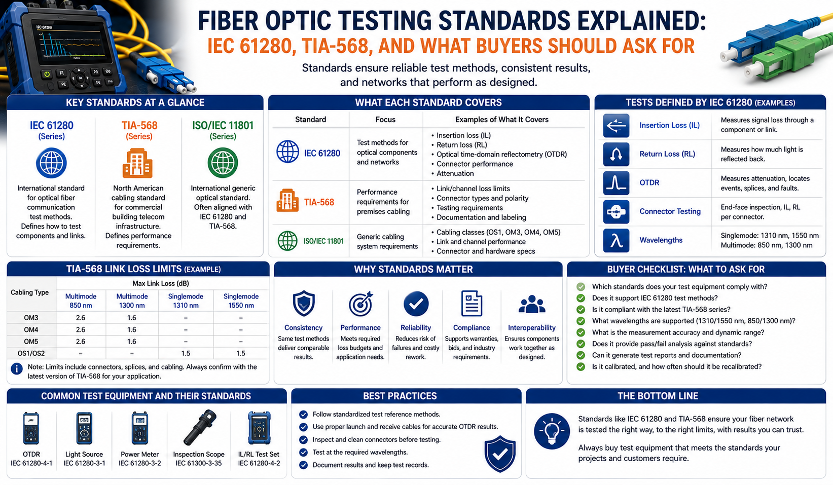
Loose particles anywhere on the contact area should be cleaned before judging Zones A and B, because debris there can migrate inward under mating pressure. Several cleaning attempts may be needed, and anything still present after cleaning is treated as a defect. The standard also states plainly that visual inspection does not replace optical qualification, so a clean end face still needs attenuation and return loss measurement. For anyone building an inspection workflow, a proper fiber end face inspection scope is the difference between guessing and knowing.
Field Habits That Keep All Three Layers Healthy
Good technique protects core, cladding, and coating without much conscious effort. Cap every connector the moment it is unmated, because an open ferrule in a dusty comms room is a problem waiting to happen. Never assume a factory-sealed patch cord is clean either, since caps themselves shed plastic particles and mold release residue.
The workflow experienced techs run is boring and it works: clean, inspect, clean again if needed, inspect again, then mate. Dry cleaning with a one-click pen handles most dust, while a wet-to-dry method with fiber-grade wipes deals with oils and stubborn residue.
Habits worth building:
- Inspect before you connect, every time
- Clean both sides of the mate, not just the jumper in your hand
- Use fiber-specific wipes and solvent rather than generic isopropyl swabs
- Replace cassette tape and pen tips on schedule instead of when they visibly fail
- Hold bend-radius discipline, since coating damage today becomes a break next winter
Bottom Line
Learn the three C’s of fiber properly and much of this trade stops feeling mysterious. Core carries the light, cladding keeps it contained, coating keeps the glass intact long enough to matter. Once that clicks, contamination control stops being a chore and starts being the obvious thing to do.
Next step: before the next install, audit what is actually in the kit. If a cleaner pen, cassette, or fiber-grade wipes are missing, sort out your cleaning setup here and pair it with a scope so you are inspecting rather than guessing.
Frequently Asked Questions
What are the three C’s of fiber optic cable?
The three C’s are core, cladding, and coating. The core is the glass center that carries light, the cladding is the surrounding glass layer that reflects light back inward, and the coating is the polymer layer protecting the glass from moisture and abrasion. Together they describe the basic physical construction of a single optical fiber.
Are the three fibers in a cable the same as the three C’s?
No, and the wording trips people up regularly. Three fibers simply means three strands inside a bundle, each with its own core, cladding, and coating. The three C’s describe layers within a single strand.
Do the three C’s change between single-mode and multimode?
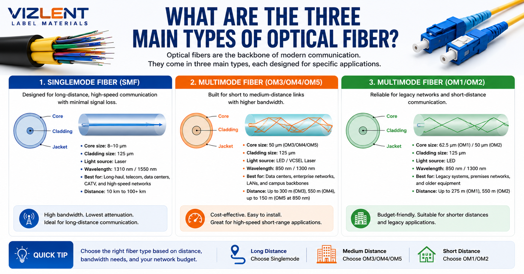
The structure is identical and only the dimensions shift. Single-mode uses a core of roughly 9 µm while multimode uses 50 or 62.5 µm, and both use 125 µm cladding on standard telecom and datacom fiber. That shared cladding diameter is why the same connectors and cleavers work across both types.
Why is standard telecom fiber cladding usually 125 microns?
It is a manufacturing and tooling convention rather than a physical requirement. Fixing the outside diameter at 125 µm lets connectors, ferrules, splice sleeves, and cleavers work across single-mode and multimode without redesign. Specialty fibers outside communications do use other cladding diameters.
What is the difference between fiber coating and a buffer?
The coating is the acrylate layer applied to the bare glass during manufacturing, typically 250 µm in outside diameter. A buffer is applied over that coated fiber as part of cable construction, with a 900 µm tight buffer common in indoor cable and pigtails. The coating is one of the three C’s while the buffer is not.
What happens if the fiber coating gets damaged?
Damaged coating exposes bare glass to moisture and abrasion, which lets microscopic surface flaws grow under tension. The fiber may still pass a test today and fail weeks or months later. Splice protection sleeves and correct tray routing exist to protect the stripped section during termination.
Which standard decides whether an end face passes or fails?
IEC 61300-3-35 sets the visual inspection criteria for fiber optic connector end faces, with the 2022 third edition currently in force. Under that edition, pass or fail rests on Zone A and Zone B, while Zones C and D no longer carry inspection requirements. Confirm which edition a project spec references before disputing a result.
Does end face inspection replace insertion loss and return loss testing?
No. IEC 61300-3-35:2022 states directly that visual inspection is not a substitute for optical qualification. Inspection tells you whether an end face is fit to mate, while attenuation and return loss measurements tell you whether the link actually performs.