Conduit and Innerduct Installation causes fiber loss when the pathway forces the cable below its rated minimum bend radius, because a bend tighter than the cable rating increases radiative loss from the guided light instead of keeping it confined in the core. The damage is rarely a snapped fiber. It is a fraction of a decibel on an OTDR trace that nobody can locate three years later.
Duct systems fail quietly. A sweep that looks generous in the trench can tighten once the backfill settles. A coil of slack racked in a manhole gets smaller every time a crew reworks the vault, and the loss climbs with it.
Standards note. Requirements vary by cable construction, pathway type, jurisdiction, and project specification. Always verify the current applicable standard and the cable manufacturer's installation requirements before pulling fiber.
Why Bends Steal Light Before They Break Glass
Optical fiber confines light within the core because of the refractive index difference between core and cladding. Bending the fiber changes the propagation conditions of the guided mode, so part of the mode field interacts differently with the curved waveguide and radiates away. Nothing about the cable has to look damaged for that loss to appear.
Bend loss is strongly wavelength dependent, which is the most useful diagnostic fact in the field. A radius that costs almost nothing at 1310 nm can cost several times more at 1550 nm, and more again at 1625 nm. Longer wavelengths carry a larger mode field, so they sit closer to the radiation condition at any given radius.
Two distinct mechanisms are at work, and they call for different fixes:
- Macrobend loss. A visible curve tighter than the rated radius. Caused by tight sweeps, over-coiled slack, undersized vault racking, and cable pulled hard around a corner.
- Microbend loss. Small-scale lateral stress along the cable. Caused by grit inside the duct, crushed in an overfilled pathway, over-tightened cable ties, and a helixed innerduct pressing the cable against a wall.
- Long-term reliability. Excessive installation stress can reduce long-term cable reliability, particularly when it introduces mechanical damage or persistent deformation. The degree of risk depends on cable construction, applied load, bend geometry, and site conditions.
The Bend Radius Numbers That Govern Every Pull
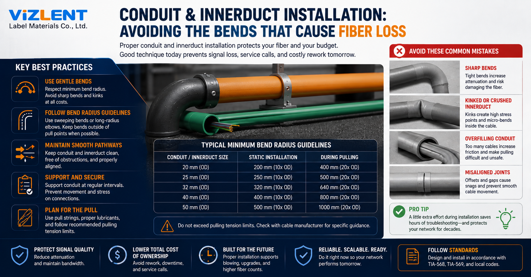
A common ANSI/TIA-568.3 baseline for many fiber cable constructions is 10 times the cable outside diameter after installation, and 20 times the outside diameter under the cable's rated tensile load. Some categories carry absolute figures instead, such as inside plant cables with four or fewer fibers rated at 25 mm at rest and 50 mm under a 220 N (50 lbf) pull. The cable manufacturer's specification takes precedence whenever it is more restrictive than the standard.
The allowable radius is generally tighter after installation because the cable is no longer under its installation pulling load. Under tension, aramid strength members stretch and the jacket presses hard against the duct wall at every corner. Fibers inside a loose tube are also pushed toward the outside of the curve, where strain is highest, and they relax back toward the tube's neutral position once the pull stops.
Bend Radius Examples
- During the pull, at rated tension: 20 × cable OD → 200 mm minimum radius for a 10 mm OD cable.
- After installation, with no load: 10 × cable OD → 100 mm minimum radius for a 10 mm OD cable.
- ISP cable with 4 fibers or fewer, at rest: 25 mm fixed → 25 mm minimum radius.
- ISP cable with 4 fibers or fewer, under 220 N: 50 mm fixed → 50 mm minimum radius.
Bend-insensitive fiber changes fiber-level macrobend performance, not the finished cable's bend radius rating. ITU-T G.657 specifies design radii of roughly 10 mm for A1, 7.5 mm for A2, and 5 mm for B3, all of which are tighter than conventional G.652.D fiber tolerates. Jacket, buffer tubes, and strength members still dictate what may be bent inside a duct, so a G.657 build does not license a tight sweep.
How Pathway Geometry Sets the Tension Ceiling
Every bend in a run multiplies pulling tension rather than adding to it, following the capstan relationship between friction coefficient and total wrap angle. Two 90-degree bends do not cost twice what one costs. They compound, and a run with four quarter bends can demand several times the force of a straight shot at the same length.
Telecommunications pathway specifications commonly limit accumulated bends to 180 degrees between pull points, and many institutional specifications applying TIA-569-E are written that way. Electrical codes such as the NEC apply their own bend limits to raceways, and those limits are not always the governing requirement for an optical pathway. The applicable code, pathway standard, and project specification should all be checked before the route is fixed.
A useful conduit and innerduct installation diagram plots pull points against cumulative bend degrees rather than distance alone. Back-to-back 90s near the end of a run are the worst case, because tension has already built across the full length before it hits the multiplier. Long runs may justify an intermediate pull point even on a straight route, simply because sidewall friction accumulates.
Design moves that keep tension inside the cable rating:
- Specify long-radius sweeps rather than field-bent or standard 90-degree elbows at every direction change.
- Break the route with handholes or vaults so no segment exceeds the accumulated bend limit in the governing specification.
- Place the heaviest bend concentration near the start of the pull, so tension builds after the corners rather than before them.
- Use a mid-assist figure-eight or a powered mid-point feed on long backbone runs instead of increasing winch force.
Fill Ratio Is the Other Half of the Bend Problem
Fill and bending are the same problem viewed from two angles. A crowded duct removes the clearance a cable needs to take a corner on its own radius, so fill decisions quietly set the bend geometry. Fiber pathway design has to account for both at the same time.
NEC Chapter 9, Table 1 provides commonly cited raceway fill percentages of 53 percent for one, 31 percent for two, and 40 percent for three or more. Telecommunications pathways should also be designed to the applicable TIA pathway standard, the project specification, and the cable manufacturer's requirements. Telecom practice typically runs tighter than any code ceiling, with many designers planning an initial fill near 25 percent and treating 40 percent as a working maximum.
Conduit Fill Examples
One cable:
- Commonly cited raceway fill percentage: 53%
- Typical fiber pathway design target: 30% to 40%
Two cables:
- Commonly cited raceway fill percentage: 31%
- Typical fiber pathway design target: 25% to 31%
Three or more cables:
- Commonly cited raceway fill percentage: 40%
- Typical fiber pathway design target: 25% initial fill, with 40% as the ceiling
There is also a jamming condition worth designing around. When exactly three cables are pulled and the ratio of duct inside diameter to cable outside diameter falls between about 2.8 and 3.2, cables can wedge side by side inside a bend rather than nesting. Shifting the duct size one trade size in either direction removes the risk at almost no cost.
Choosing and Placing Innerduct Without Introducing Bends
Sound fiber pathway design treats innerduct as capacity rather than packaging. Innerduct subdivides a large bore so future pulls do not entangle live cable, which is the difference between a spare pathway and a permanently occupied one. Common practice places two to four 1.25 inch innerducts inside a 4 inch conduit, which is why many high-count OSP cables are engineered to stay near or below one inch outside diameter.
Outside-plant innerduct commonly uses HDPE, while indoor systems use materials selected for the required flame, smoke, temperature, and mechanical ratings. Corrugated construction has less memory, bends around a large radius without collapsing the bore, and resists crush well. Smoothwall gives lower friction for long mechanical pulls and for cable jetting.
Innerduct can elongate or shift during placement, so installation should account for manufacturer-specified pulling tension, bend radius, and slack requirements. The placement errors that create hidden bends:
- Helixing. Innerduct that twists as it is pulled corkscrews inside the bore. That adds a wrap angle the route design never counted, and cable tension rises sharply as a result.
- No slack allowance. Innerduct can relax after installation. Extra length pulled into vaults keeps that recovery from drawing a bend tight at the duct mouth.
- Unracked manhole transitions. Innerduct running continuously through a vault needs enough slack to be racked at or above the cable's minimum bend radius.
- No pull tape. Retrofitting a line into occupied innerduct risks abrasion against live cable. Pre-installed flat pull tape avoids the rope burn-through that round rope can cause at bends.
A Field Sequence That Protects the Cable
A written conduit and innerduct installation manual belongs on the truck, because sequence matters as much as component selection. Proving the pathway comes first. Rod and mandrel every segment to confirm the bore is clear, round, and free of collapsed sections before a reel is mounted.
Tension control follows. Load is applied to the strength member through a rated pulling eye or grip with a swivel, never to the fibers or the jacket alone. Use only a pulling lubricant confirmed compatible with the cable jacket and approved by the cable manufacturer.
Pull day sequence:
- Rod, mandrel, and proof each duct section, and record any obstruction location.
- Calculate expected tension from length, fill ratio, accumulated bend degrees, and coefficient of friction.
- Set a breakaway swivel or tension-limiting winch below the cable's manufacturer-rated maximum. Depending on construction, ratings can range from low hundreds of pounds to 600 lbf or more for some OSP cables.
- Apply compatible lubricant continuously at the feed point rather than in a single slug at the start.
- Station a spotter at every bend and every vault, and use quadrant blocks or sheaves to hold radius at direction changes.
- Figure-eight the cable at mid-assist points. Never coil it, because coiling induces twist.
- Rack slack in vaults at or above the static bend radius, and secure it without over-tightening ties.
Termination and splicing follow the same discipline. Staging fiber optic cleaning tools at both ends before the first connector is mated keeps contamination out of the acceptance numbers, since a dirty end face can easily be mistaken for a pathway fault.
Verifying the Route Before You Sign It Off
Acceptance testing is where pathway problems either surface or get buried. Bidirectional OTDR testing at 1310 nm and 1550 nm on singlemode is the standard method. A bend typically shows substantially greater loss at the longer test wavelength, while a splice generally shows much less wavelength dependence, and connector events are often reflective, although contamination and other conditions can complicate the signature.
Interpretation depends on clean optics, which puts inspection ahead of testing rather than after it. A launch cord with a contaminated end face inflates every event on the trace and sends crews looking for a bend that does not exist. Reference-grade results start with an end face verified against IEC 61300-3-35 using a fiber inspection probe.
Signatures worth knowing on the trace:
- Bend event: non-reflective step, loss noticeably higher at 1550 nm than at 1310 nm, no reflectance spike.
- Fusion splice: non-reflective, low loss, limited wavelength dependence.
- Connector or mechanical splice: commonly reflective, with loss influenced by contamination and end face condition.
- Crushed duct section: elevated attenuation slope over a length rather than a single point event.
What Conduit and Innerduct Installation Cost Actually Buys
Conduit and innerduct installation cost is dominated by labor and construction methods rather than by the duct itself. The 2025 Fiber Deployment Cost Annual Report from the Fiber Broadband Association and Cartesian reports a median new-conduit underground deployment cost of $18.50 per foot, against $15.00 per foot where existing conduit is used and $10.32 per foot for direct burial. Those medians reflect reported deployment cost across surveyed operators and contractors, covering labor and materials rather than a single contractor sell price.
Construction technique drives much of the spread in the same report, with trenching at a median of $19.00 per foot and plowing clustering around $11.88 per foot. Read against those figures, bend discipline is inexpensive. Adding a vault to split a run into two compliant segments, or specifying long-radius sweeps instead of standard elbows, costs a fraction of what a single mid-span replacement after a failed acceptance test consumes.
Mistakes That Show Up Six Months Later
The most expensive errors are the ones that pass a same-day test. Slack coiled tightly around a bracket, an innerduct crimped by a vault lid, or a cable tie torqued down by a crew tidying a rack all add attenuation slowly. By the time the link fails a service threshold, the crew that built it has moved on and the as-built drawing shows a straight line.
None of these appear as steps in a conduit and innerduct installation guide, because they are habits rather than procedures. Documentation is the countermeasure that costs nothing. Record sweep radii, accumulated bend degrees per segment, fill ratio, measured pull tension, and baseline OTDR traces. That record gives the next technician a comparison point instead of a guess, and it turns a warranty conversation into a five-minute review.
Recurring failure patterns in duct-based plant:
- Slack stored in tight coils below the static bend radius instead of in figure-eight racks.
- Cable ties tightened to the point of visible jacket deformation.
- Innerduct terminated flush at a duct mouth, forcing the cable to bend against a sharp edge.
- Reusing legacy conduit without proofing it, then blaming the new cable for the loss.
Build the Pathway Once
A duct system is the only part of a fiber plant that is genuinely difficult to change later, which makes bend discipline the highest-leverage decision on the job. Design the route to a bend budget, prove every segment before the pull, and keep tension inside the cable's rated limit. Document what was built, because the link that certifies cleanly on day one is the one that still certifies in year ten.
Before the next pull, stage calibrated OTDR and loss test equipment, inspection scopes, and cleaning consumables at both ends of the route. Confirming the gear list during planning, rather than on pull day, is what keeps bend faults cheap to find and cheap to fix.
Frequently Asked Questions
What is the minimum bend radius for fiber optic cable in conduit?
A common baseline for many fiber cable constructions is 20 times the cable outside diameter under rated pulling tension and 10 times the outside diameter once installed and unloaded. Some inside plant categories use fixed values instead, such as 25 mm at rest and 50 mm under a 220 N pull for cables with four or fewer fibers. The manufacturer datasheet governs, since specific constructions can be more restrictive than the standard.
How many degrees of bend are allowed between pull points?
Telecommunications pathway specifications commonly limit accumulated bends to 180 degrees between pull points, and many project specifications applying TIA-569-E are written that way. Electrical codes apply their own raceway bend limits, which are not always the governing requirement for an optical pathway. Check the applicable code, pathway standard, and project specification before finalizing the route.
What fill ratio should fiber conduit be designed to?
NEC Chapter 9, Table 1 provides commonly cited raceway fill percentages of 53, 31, and 40 percent, but telecommunications pathways should also follow the applicable TIA pathway standard and the project specification. Many designers plan an initial fill near 25 percent with 40 percent as a working ceiling, leaving capacity for future pulls. Watch the jamming condition when pulling exactly three cables, since a duct-to-cable diameter ratio between roughly 2.8 and 3.2 invites wedging in bends.
Does bend-insensitive fiber remove the need for bend radius limits?
No. ITU-T G.657 specifies design radii near 10 mm for A1, 7.5 mm for A2, and 5 mm for B3, which describes fiber-level macrobend performance rather than the finished cable rating. Jacket, buffer tubes, and strength members set the cable's real limit, so duct and racking rules stay unchanged.
How do I tell a bend from a bad splice on an OTDR trace?
Compare loss at 1310 nm and 1550 nm on the same event. A bend typically shows substantially greater loss at the longer wavelength, while a fusion splice generally shows much less wavelength dependence. Connector events are often reflective, though contamination and end face condition can complicate the reading, so testing bidirectionally is worth the extra pass.
What is the maximum pulling tension for fiber optic cable?
There is no single figure, because cable construction controls it. Set the pulling limit below the manufacturer-rated maximum for the specific cable, which can range from low hundreds of pounds to 600 lbf (2,670 N) or more for some outside plant constructions. Apply tension to the strength member through a rated pulling eye and swivel, and use a breakaway swivel as insurance against overload.
Why does innerduct twist increase pulling tension?
Twisted innerduct helixes inside the outer conduit, which adds a wrap angle that the original route design never counted. Because tension multiplies with total bend angle rather than adding, a helixed run can demand far more force than its straight-line length suggests. Keeping the innerduct untwisted during placement and allowing slack for post-installation relaxation prevents it.
Can innerduct be added to conduit that already carries fiber?
It can, but the existing cable must be protected during the pull, since a rope or tape dragging across live cable can abrade the jacket at bends. Pre-installed flat pull tape and adequate remaining capacity are the two conditions that make it viable. Where neither exists, a new bore is often cheaper than the outage risk.



It is widely applicable in fiber-optic communications, where they allow transmission over longer distances and at higher bandwidths than wire cables.
Increase in internet penetration is the primary growth factor of the global optical fiber market.
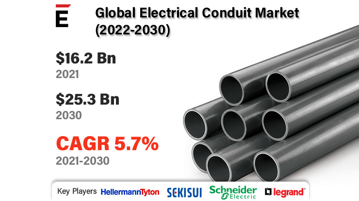
In addition, plastic conduits are made mostly of PVC that provides advantages of lower costs of installation, lighter weight, non-conductive, resistance to ultraviolet rays and corrosion.The choice between metal or plastic conduit is mainly influenced by site conditions, type of building, temperature of the location, and exposure to corrosive or damp conditions among others.
Plastic conduits are being increasingly used for all types of installation work, both for commercial and domestic wirings in IT & telecom sector.Get Access to sample pages @ https://www.trendsmarketresearch.com/report/sample/13364 These flexible plastic conduits are made in all sizes from 16mm to 50 mm in external diameter.
Thermal expansion of a plastic conduits is about six times that of steel.
Depending on mode, the market is bifurcated into single mode and Multimode.By product type, it comprises glass optical fiber and plastic optical fiber.