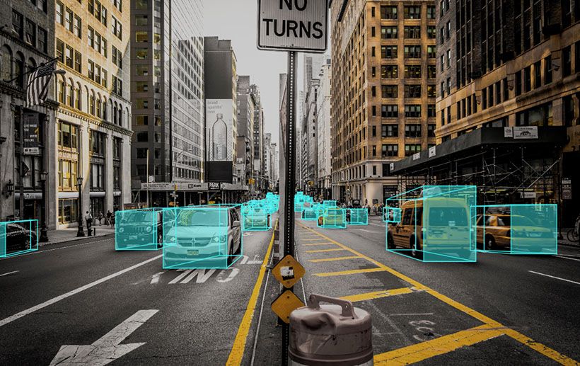


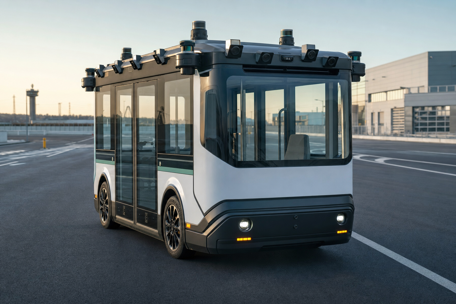
Autonomous vehicles AI depends on reliable sensor timing and predictable end-to-end response, not camera count or accelerator speed alone. Multiple cameras expand coverage and improve scene understanding, but they also increase bandwidth, synchronization, decoding, memory, heat, and failure-handling requirements. A suitable edge computer must ingest every required stream, run the complete perception pipeline, and deliver verified outputs within the vehicle's latency budget under real operating conditions.
When evaluating Autonomous vehicles AI, buyers should start with the operational design domain: where the vehicle will travel, how fast it moves, which objects it must detect, and what the system must do when a sensor or model becomes uncertain.
Quick Decision Points for Autonomous Vehicles AI
- Coverage: fields of view, overlap, blind spots, and the minimum number of cameras needed for the use case.
- Timing: frame synchronization, timestamp accuracy, sensor-to-decision latency, and tail latency.
- Data path: camera interface, deserialization, decoding, memory movement, inference, and output transport.
- Compute: model mix, precision, resolution, frame rate, and simultaneous workloads.
- Vehicle integration: power input, ignition behavior, CAN or serial interfaces, positioning, and networking.
- Environment: vibration, connectors, cable length, temperature, dust, moisture, and electromagnetic conditions.
- Recovery: degraded operation after a camera, cable, storage, network, or AI process fault.
- Validation: measurable pass/fail criteria on the target route and enclosure.
The selection is complete only when these requirements are linked to a test. A product page can identify candidate features; it cannot prove performance in a particular vehicle.
Why Do Autonomous Vehicles Use Multiple Cameras?
Multiple cameras can provide wider coverage, overlapping views, depth cues, and specialized perspectives for forward perception, side awareness, rear monitoring, cabin or cargo observation, and close-range maneuvering. The exact topology depends on the vehicle and task.
An autonomous shuttle in a controlled campus, a low-speed delivery robot, an agricultural vehicle, and a high-speed road vehicle do not share one correct camera layout. Each has different stopping distances, obstacle classes, lighting conditions, legal requirements, and acceptable fallback behavior.
Overlap is useful only when timing is controlled
Overlapping cameras can help track an object as it moves between views or provide redundancy when one view is blocked. If frames are not aligned closely enough, however, the system can fuse observations from different moments and create position errors for moving objects.
Record the exposure time, timestamp source, trigger method, transport delay, and synchronization tolerance. Do not assume that streams arriving at the same software process represent the same instant.
Resolution and frame rate create a system cost
Higher resolution can reveal smaller or more distant objects, while higher frame rate reduces the motion between observations. Both increase data bandwidth and processing demand. The right setting is the lowest one that still satisfies the detection, localization, and reaction requirement with adequate margin.
Buyer check: Request a bandwidth calculation for the actual number of cameras, format, resolution, and frame rate. Then verify it with all streams active.
What Does Low Latency Mean in a Vehicle?
Low latency means the perception result arrives early enough for the downstream planning and control system to respond safely. It should be measured from sensor capture to the moment a usable, timestamped output reaches the next subsystem.
Inference time is only one component:
- Camera exposure and readout.
- Serialization and transport.
- Deserialization, capture, and buffering.
- Image preprocessing.
- AI inference.
- Tracking and sensor fusion.
- Planning or event logic.
- Communication to the controller.
- Controller and actuator response.
ETSI Multi-access Edge Computing use cases describe latency-sensitive local analysis for connected-vehicle and roadside applications. That supports the architectural reason for placing selected processing near the data source, but it does not create one universal latency target for every autonomous vehicle.
Average latency is not enough
Measure percentiles, maximum observed delay, and the conditions that cause long tails. Thermal throttling, storage activity, logging, network traffic, memory contention, and a difficult visual scene can all change timing.
The validation should also detect stale results. A fast output based on an old or incorrectly timestamped frame is not useful simply because the inference step was short.
How Does GMSL2 Support Multi-Camera Vehicles?
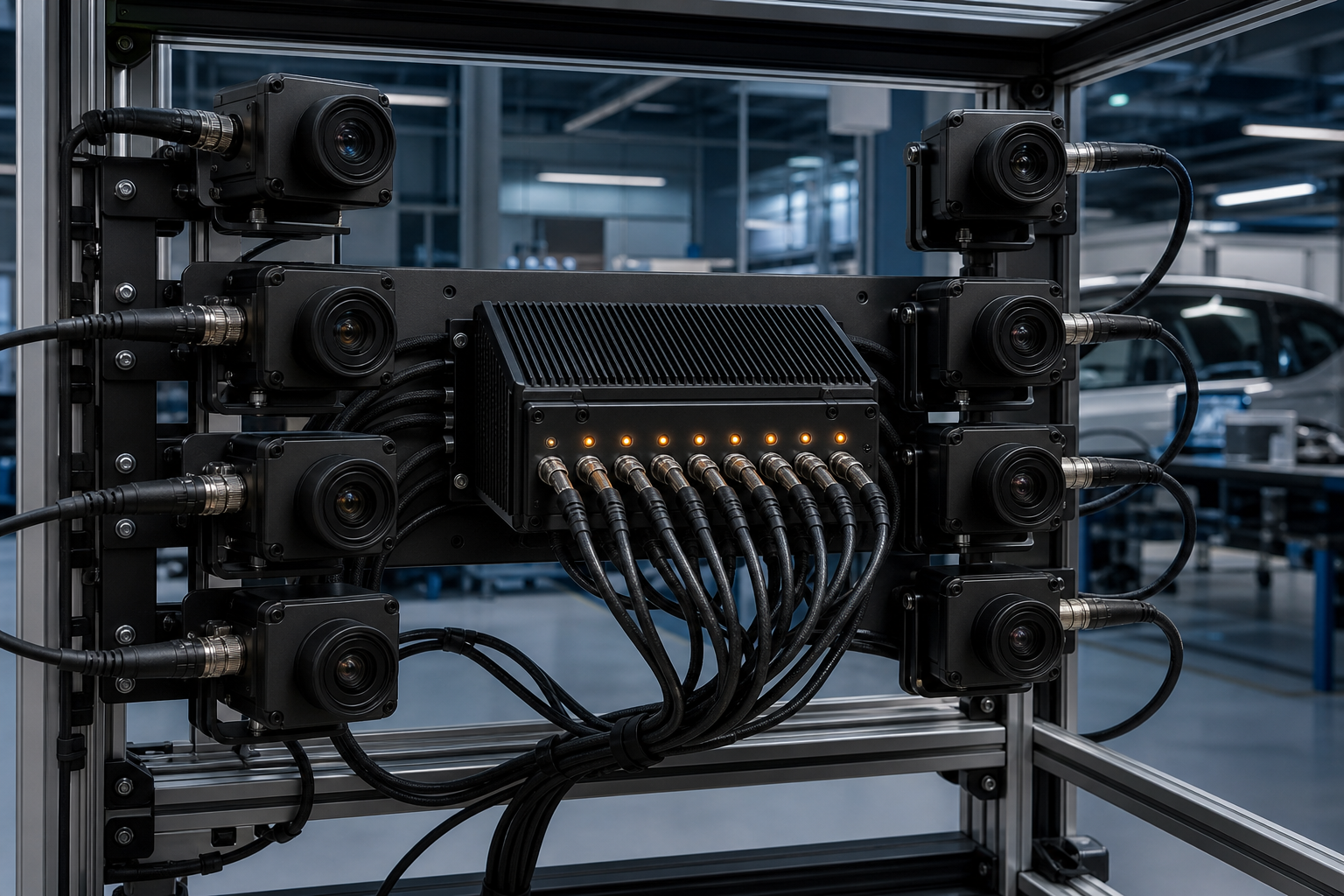
Gigabit Multimedia Serial Link 2, or GMSL2, is commonly used to transport automotive camera data over robust cabling through serializer and deserializer hardware. Its practical value depends on the complete camera ecosystem: supported sensors, deserializer, drivers, connectors, cable assemblies, synchronization, and the selected Jetson software release.
What to verify
- Exact camera model and image sensor.
- Serializer and deserializer compatibility.
- Supported number of simultaneous streams.
- Resolution, format, and frame-rate limits.
- Triggering and synchronization behavior.
- Cable type, length, connector, and bend limits.
- Driver and device-tree support for the software baseline.
- Recovery after a camera is disconnected or produces errors.
Common mistake: Buying an “eight-camera” computer before confirming that all eight intended camera modules can run simultaneously with the required format and synchronized timing.
Match Compute to the Whole Perception Stack
An autonomous system may run object detection, lane or free-space segmentation, depth estimation, tracking, localization, driver or cabin monitoring, recording, and communications at the same time. Size compute from this combined load.
Step 1: Establish the model baseline
For every model, record:
- Model version and architecture.
- Input size and batch behavior.
- Precision and inference runtime.
- Target frame rate.
- Preprocessing and post-processing.
- CPU, GPU, accelerator, and memory use.
Step 2: Add non-AI workloads
Include camera capture, video encoding or recording, localization, CAN messaging, diagnostics, user interfaces, encryption, and remote management. These tasks can compete for memory and CPU time even when the AI accelerator appears underused.
Step 3: Test concurrency
Run all required streams and processes together. Record dropped frames, queue depth, memory use, temperatures, clock frequencies, and end-to-end latency. Repeat during startup, route changes, network transfer, and storage events.
Step 4: Define capacity margin
Margin should cover model updates, difficult scenes, software overhead, and thermal conditions. It should be demonstrated by a sustained workload rather than inferred from the difference between two TOPS numbers.
Where Does the TWOWIN T808P-G Fit?
The TWOWIN T808P-G page describes an NVIDIA Jetson Orin NX-based edge computer with optional 70 or 100 TOPS configurations and eight GMSL2 camera interfaces. It also lists a published operating-temperature range of -40 to 70 degrees Celsius, vehicle-oriented ACC power behavior, optional positioning features, and multiple peripheral interfaces.
These specifications make the model a candidate for multi-camera vehicle or roadside projects when the exact camera ecosystem, software release, power behavior, enclosure, and workload have been validated. They should not be interpreted as proof that any eight cameras or any autonomous-driving stack will meet its target.
Configuration questions to send with an RFQ
- Orin NX memory and performance configuration.
- Eight exact camera part numbers and required modes.
- Deserializer and driver package.
- Required synchronization and timestamp method.
- Storage size and recording policy.
- Ethernet, CAN, serial, positioning, and wireless options.
- Input-voltage range and ignition sequence.
- Mechanical mounting, connectors, and cable assemblies.
- Thermal conditions and enclosure.
- Software image, JetPack release, and update ownership.
Vehicle Power, Startup, and Shutdown Matter
Vehicles present voltage variation, transients, ignition states, and abrupt shutdown risks that a laboratory power supply does not reproduce. The edge computer, storage, and cameras must start in the correct order, detect ignition changes, save critical data, and avoid corrupting the file system.
Validate the power sequence
- Cold start at the lowest specified voltage.
- Operation during expected voltage variation.
- Ignition or ACC on/off behavior.
- Controlled shutdown timing.
- Restart after an interrupted shutdown.
- Power consumption in sleep or off states.
Use appropriate vehicle power protection and qualification for the target market. A wide voltage input on a product page does not replace system-level transient and electromagnetic compatibility testing.
Environmental and Mechanical Validation
Temperature is only one environmental variable. Camera connectors, coaxial cables, storage devices, and mounting hardware must also tolerate vibration, shock, moisture, dust, and repeated service.
Test the complete installed assembly. A computer can remain within temperature limits while a poorly restrained camera cable produces intermittent errors. Likewise, a connector can be mechanically robust while its driver fails to recover after a brief link interruption.
Buyer check: Define how the system reports a degraded camera and whether the vehicle slows, stops, transfers control, or continues with reduced capability.
A Practical Acceptance Test
Camera ingestion
- All cameras start correctly after repeated cold boots.
- Required streams operate simultaneously.
- Timestamps and synchronization stay within the specified tolerance.
- No unexplained dropped frames occur during the test duty cycle.
Perception timing
- End-to-end latency is measured at defined points.
- Percentile and maximum limits are met.
- Results are rejected when frames are stale or synchronization is invalid.
- Performance remains stable at worst-case temperature.
Vehicle integration
- CAN, positioning, Ethernet, storage, and diagnostics run concurrently.
- Ignition shutdown protects stored data.
- Network loss does not stop essential local functions.
- Watchdogs recover or place the system in the defined safe state.
Fault handling
- One camera disconnected.
- Corrupted or frozen stream.
- Storage nearly full.
- AI process crash.
- Positioning unavailable.
- Supply interruption.
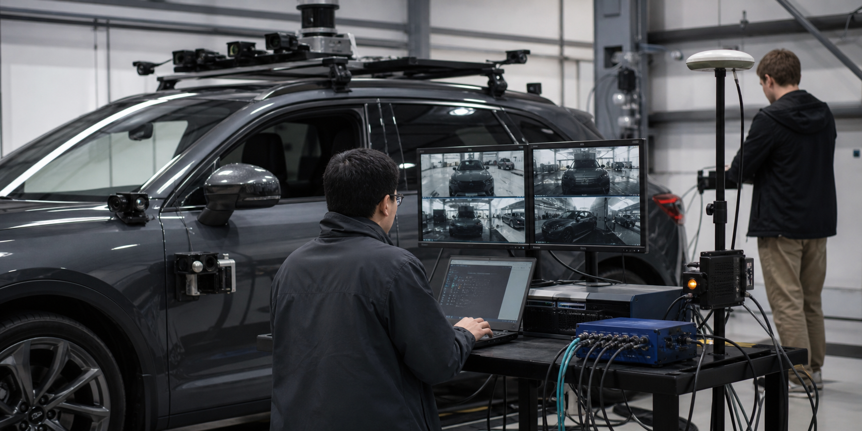
Pass/fail evidence should include logs, temperatures, timing data, software versions, and hardware configuration so the test can be repeated.
Frequently Asked Questions
Do autonomous vehicles always need eight cameras?
No. The number follows field-of-view coverage, redundancy, object range, maneuvering needs, and the operating environment. Use the smallest topology that satisfies the safety and performance requirements, then confirm bandwidth and synchronization.
Is 100 TOPS enough for autonomous vehicles AI?
It may be enough for a defined low-speed or limited-domain workload, but TOPS alone cannot answer the question. Benchmark the exact models, precision, cameras, frame rates, preprocessing, fusion, recording, and background services under sustained thermal conditions.
Why process camera data locally?
Local processing can reduce dependence on wide-area connectivity and shorten the path between sensing and a vehicle response. The architecture still needs secure updates, logging, remote diagnostics, and a clear rule for what data is transmitted.
What is the most important supplier question?
Ask for a repeatable demonstration using the intended cameras and software while measuring end-to-end latency, dropped frames, temperatures, and recovery behavior. A generic video demonstration is not an acceptance test.
Build a Measurable Vehicle Edge-AI Specification
TWOWIN can evaluate a multi-camera edge-computing request when the brief includes the vehicle type, operating speed and domain, camera part numbers, required modes, synchronization tolerance, model workload, latency limit, storage policy, positioning, CAN and network needs, power behavior, environmental conditions, and validation method. Use that specification to confirm whether the T808P-G configuration fits before committing the vehicle design.
References and Sources
- TWOWIN, NVIDIA Jetson Orin NX 8xGMSL2 T808P-G product page.
- NVIDIA Developer Blog, Implementing Real-Time Multi-Camera Pipelines with NVIDIA Jetson.
- ETSI GS MEC 002, Multi-access Edge Computing Use Cases and Requirements.
Robotics intelligence needs more than a fast AI accelerator. A practical robot must process its cameras and sensors within a predictable time, exchange data with motion controllers, fit a real powe